This article explains how architectural notations complement frameworks, providing symbolic languages to visualize software systems. Learn about core elements, characteristics of effective notation, and guidance on choosing diagramming tools to simplify complexity and enhance communication.
Introduction
Diagrams simplify complex systems, turning abstract ideas into clear visuals that everyone - technical and non-technical alike - can understand. They improve communication, support decision-making, and provide a shared understanding across teams, reducing ambiguity and errors. For architects, diagrams serve as both a communication tool and a record of design decisions, making the evolution of the architecture clearer and easier to track.
Using standard notations in diagrams ensures consistency, aids collaboration, and speeds up development by presenting the architecture in an accessible and organized manner.
What is Architecture Notation?
Architecture notation refers to the symbolic language or system used to visually represent software systems’ structure, behavior, and interactions. It transforms abstract architectural concepts into tangible diagrams, serving as a bridge between ideas and their implementation. Notation is essential for architects to communicate designs effectively with diverse stakeholders, from developers to executives.
The Purpose of Architecture Notation
- Simplifying Complexity: Software systems can be intricate, with numerous components, dependencies, and workflows. Notation simplifies this complexity by abstracting details into comprehensible visuals.
- Facilitating Communication: Notation provides a common language for stakeholders, ensuring that technical and non-technical audiences understand the architecture.
- Enhancing Documentation: Visual representations created using notations serve as enduring documentation, capturing the system’s design for future reference.
- Supporting Decision-Making: Notations help make systems more transparent, analyze trade-offs, identify bottlenecks and plan changes.
Core Elements of Notation
Architecture notation typically involves:
- Shapes: Representing components, such as systems, databases, or processes.
- Lines and Arrows: Indicating relationships, data flow, or communication between components.
- Labels: Providing essential context about each element in the diagram.
- Colors and Symbols: Highlighting specific attributes or categorizations, like dependencies, protocols, or priorities.
Commonly Used Architecture Notations
Architecture notations provide the visual language needed to describe systems effectively. Different notations have unique strengths based on the elements they emphasize, allowing architects to choose the best fit for their context.
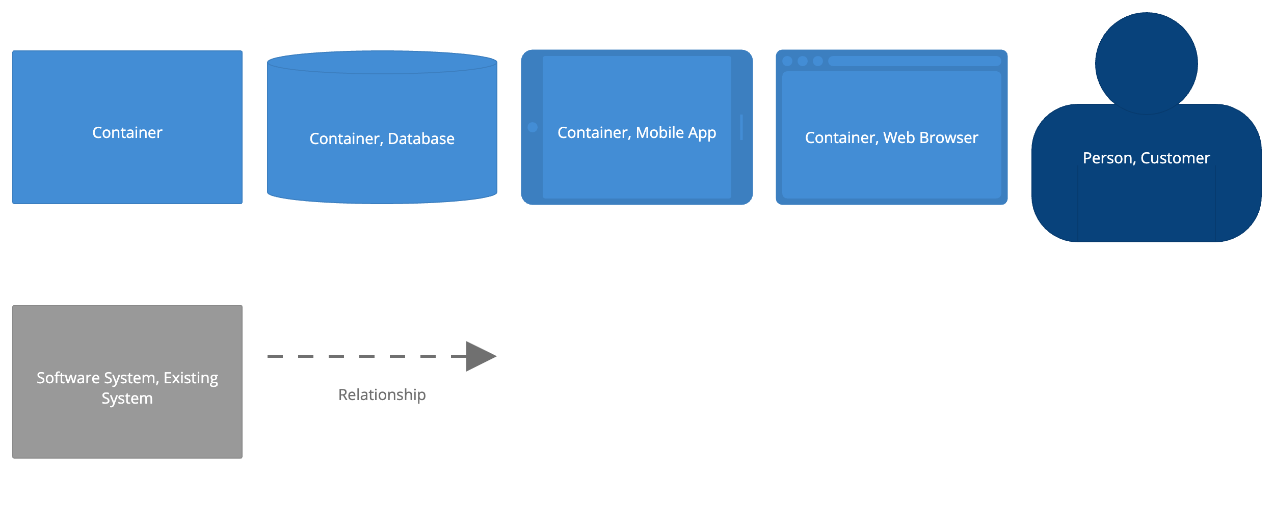
C4 Notation
Built into the C4 model, it simplifies diagramming with four layers of abstraction and focuses on clear labeling and relationships over complex symbols.
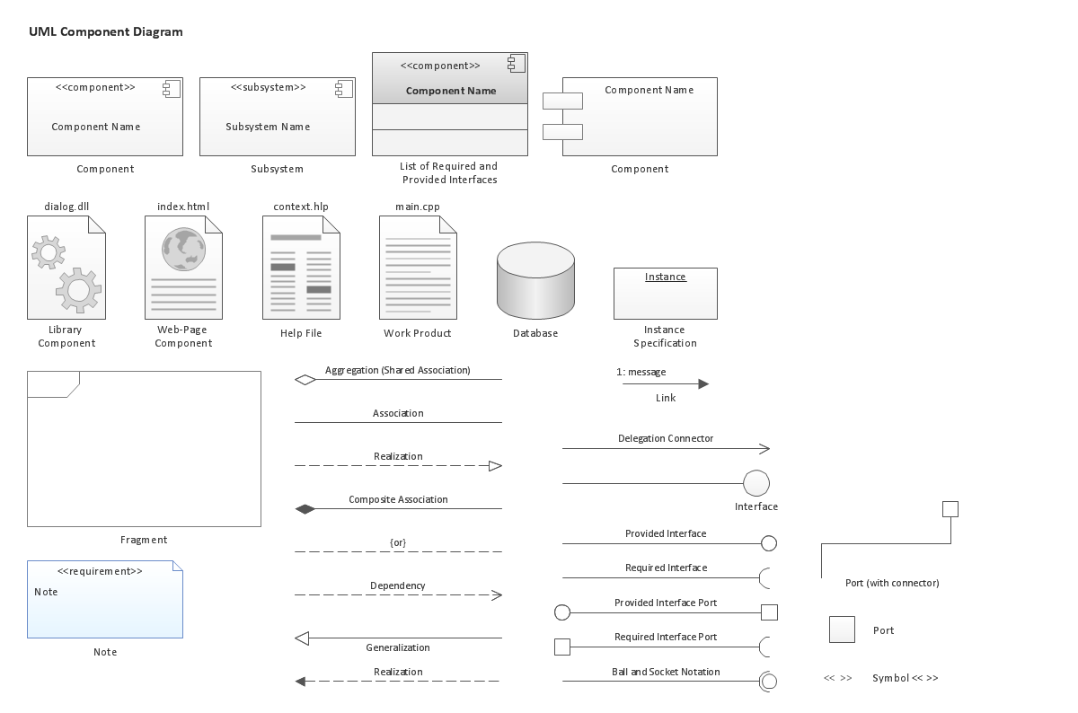
UML (Unified Modeling Language)
A standardized notation for depicting system components, relationships, and workflows. Effective for class diagrams, sequence diagrams, and activity diagrams.
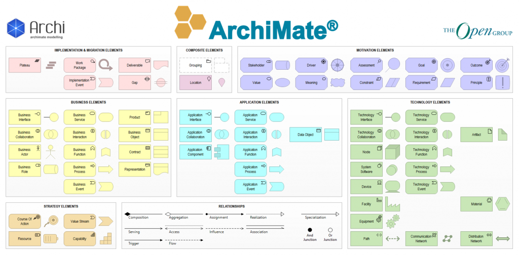
ArchiMate
A visual modeling language explicitly designed for enterprise architecture, often used with TOGAF.
Characteristics of Effective Notation
For a notation system to be effective, it must exhibit the following characteristics:
- Clarity: Visual representations should prioritize readability. Avoid overly complex symbols or layouts that might confuse the audience.
- Consistency: Use the same symbols and styles across diagrams to maintain coherence and reduce cognitive load.
- Context Appropriateness: Select a notation that aligns with the audience’s familiarity and the complexity of the system being represented. For example:
- Use UML for detailed technical design discussions.
- Opt for C4 when presenting software architecture to a mixed audience.
- Flexibility: Allow for the customization of symbols or styles to accommodate unique project needs while staying within the boundaries of the chosen notation.
Challenges and Considerations
- Overloading Diagrams: Including excessive detail can make diagrams cluttered and hard to understand. Focus on the level of abstraction relevant to the audience.
- Inconsistent Symbols: Misuse of symbols or lack of a legend can lead to misinterpretation of diagrams.
- Assumed Knowledge: Using vendor-specific icons (e.g., AWS or Azure symbols) without explanation can alienate those unfamiliar with the technology stack.
- Neglecting Updates: Failing to update diagrams as the system evolves can render documentation obsolete and misleading.
Choosing Diagramming Tools
Key Features
Choosing the right diagramming tool is essential for creating practical, maintainable diagrams. The following features should be considered when selecting a tool:
- Flexibility and support for Multiple Diagram Types: The tool should offer the flexibility to create various diagrams, such as UML, C4, flowcharts, or data flow diagrams, based on the project needs.
- Accessibility Options: The tool must provide color contrast adjustments, pattern options, and checks for visual accessibility to ensure that the diagrams can be interpreted differently without relying on color.
- Templates and Consistency: Built-in templates and standardized styles help ensure the diagrams maintain a consistent look across various abstraction levels.
- Layers Support: Quickly enabling and disabling the visibility of some aspects in groups provides an easy way to manage additional information and avoid the overhead of maintaining multiple versions of diagrams with multiple levels of detail.
- Collaboration Features: Real-time collaboration and version control capabilities allow multiple stakeholders to simultaneously contribute to and review diagrams, ensuring everyone stays aligned.
- Integration with Other Tools: The tool should integrate with other platforms, such as version control systems and documentation tools, for easy updates and collaboration.
- Exporting and Sharing: The ability to export diagrams in multiple formats (e.g., PNG, SVG, PDF) is critical for sharing across different mediums, from reports to presentations.
- Ease of Use: The interface should be intuitive and user-friendly, allowing architects to create, update, and maintain diagrams efficiently.
Selecting a tool that offers these features ensures that diagrams are practical and easy to manage throughout a project’s lifecycle.
Generic vs Specific Tools
When selecting architecture diagramming tools, we can classify them into two categories: architecture-specific tools and general-purpose tools. Each category offers distinct benefits that cater to different needs.
Architecture-specific Tools
These tools are tailored for creating, analyzing, and documenting software architectures. They typically support structured notations such as UML and ArchiMate, which enforce architectural standards and offer advanced analysis features. Architecture-specific tools provide consistency, implement standards, and facilitate in-depth modeling of complex systems. For example:
- ArchiMate (Open Group) – ArchiMate is a modeling tool built around the ArchiMate standard, enabling architects to represent layered architecture with structured views. It supports detailed templates and integrates with enterprise tools for advanced analysis.
- PlantUML – A text-based UML diagram generator, PlantUML creates diagrams from plain text descriptions. It’s beneficial for integrating architecture designs with version control systems like Git, offering flexibility and quick updates.
- Sparx Systems Enterprise Architect - This tool supports multiple diagramming types, including UML, BPMN, and ArchiMate. It’s ideal for modeling large and complex architectures and integrates well with development environments, making it suitable for enterprise-scale projects.
General-purpose Tools
These tools are versatile and can be used for various diagramming needs. While they don’t offer the deep architectural analysis of specialized tools, general-purpose tools are easy to use, provide flexibility in diagram types, and facilitate collaboration across teams. For example:
- draw.io – is a popular, free, and open-source diagramming tool used for creating a wide range of visual diagrams, including flowcharts, network diagrams, software architecture diagrams, and organizational charts. It is widely recognized for its simplicity, flexibility, and robust features that cater to individuals, teams, and organizations.
- Excalidraw is an online, open-source tool for creating hand-drawn diagrams and illustrations. It is lightweight and intuitive and ideal for sketching quick visuals or collaborative brainstorming. Its focus on simplicity and flexibility makes it a favorite for teams and individuals alike.
- Miro – Miro provides an intuitive, collaborative whiteboard for creating architecture diagrams. It’s excellent for brainstorming and collaborative work, integrating seamlessly with platforms like Jira and Confluence for team alignment.
- Lucidchart – Lucidchart is known for its ease of use and robust collaboration features. It offers a variety of templates, including UML, and integrates well with Google Workspace, making it suitable for teams across different industries.
- Microsoft Visio – Visio has a broad template library, including UML and other architecture notations. Integrated with Microsoft Office 365, it’s highly accessible for teams working within the Microsoft ecosystem.
Recommended Reading
Articles
- Brown, S. “Choose Tooling”. List of tools suitable for diagrams.
Books
- Richards, M., & Ford, N. (2020). Fundamentals of Software Architecture: An Engineering Approach . O’Reilly Media.
- Chapter 21: Diagramming and Presenting Architecture
General Guidance on the diagramming process and overview of existing diagramming tools and frameworks.
- Chapter 21: Diagramming and Presenting Architecture
- Read, Jacqui. Communication Patterns: A Guide for Developers and Architects . O’Reilly Media, 2024.
- Chapter 5: Notation
Chapter 5 of Communication Patterns emphasizes the importance of selecting appropriate notation to create clear, practical diagrams tailored to the audience’s needs. It highlights common pitfalls, such as overusing icons, breaking conventions, and failing to include legends, which can lead to confusion and miscommunication. The chapter advises balancing simplicity and detail, maintaining consistency, and layering information to make diagrams accessible and valuable for diverse stakeholders.
- Chapter 5: Notation