This article provides an overview of the 4+1 Architectural Framework.
The 4+1 View Model, introduced by Philippe Kruchten in 1995, is a conceptual framework used to describe software architecture from multiple perspectives. It organizes architectural descriptions into five distinct views, each addressing specific concerns of different stakeholders involved in the software development process. The model provides a comprehensive and systematic approach for analyzing and documenting complex software systems.
Structure
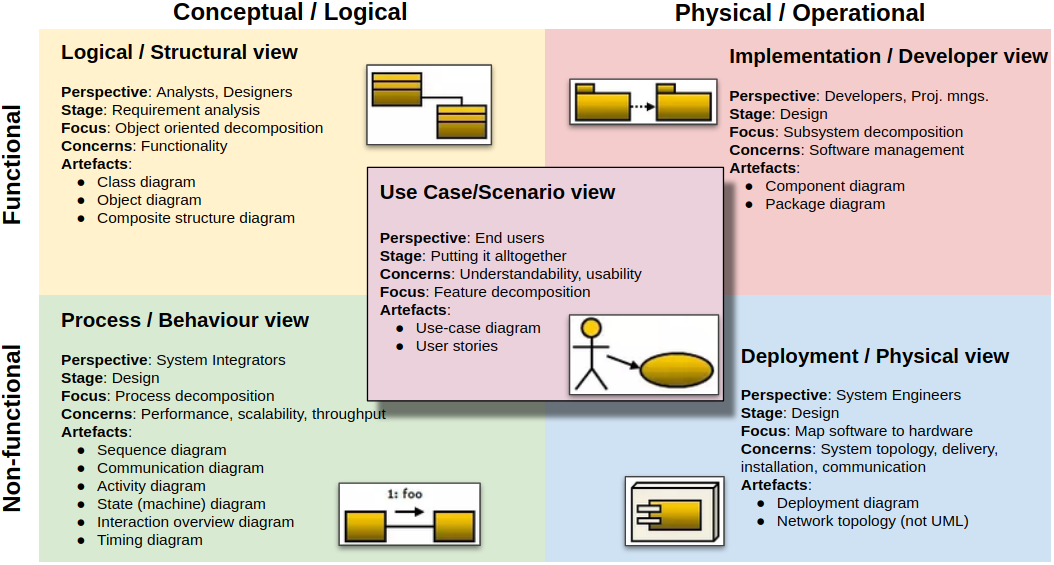
The principal motivation behind the 4+1 model is the recognition that a single architectural representation cannot adequately capture all the concerns of diverse stakeholders such as end-users, developers, testers, system engineers, and project managers. To address this, the model separates architectural descriptions into five interrelated views:
- Logical View – Describes the system’s functional structure and key abstractions.
- Process View – Focuses on runtime processes, concurrency, and system behavior.
- Development View – Represents the static organization of the source code and modules.
- Physical View – Maps software components to physical hardware infrastructure.
- Scenarios View ("+1") – Illustrates how the system behaves through representative use cases.
Each view is a projection of the system from a different angle, and the Scenarios View serves to cross-link the others through examples of typical interactions.
Logical View
The logical view captures the system’s static structure regarding classes or domain concepts and their collaborations. It supports the specification of services, behaviors, and responsibilities related to functional requirements. UML class diagrams or ER diagrams are commonly used to express this view.
- Purpose: To describe the system’s functional structure using object-oriented or domain-driven abstractions.
- Key Stakeholders: Software designers, application developers.
- Concerns:
- Classes, entities, and their relationships (e.g., inheritance, associations).
- Domain modeling and functional decomposition.
- Reuse of design patterns and encapsulation of logic.
- What is irrelevant:
- Execution environment or process scheduling.
- Source code file structure or physical deployment.
Process View
The process view addresses non-functional properties such as scalability and responsiveness. It identifies which components are active concurrently and how they interact at runtime. This view is essential for ensuring that timing, throughput, and fault-isolation requirements are met.
- Purpose: To model the dynamic aspects of the system, including process concurrency and inter-process communication.
- Key Stakeholders: Systems engineers, performance analysts, architects.
- Concerns:
- Processes, threads, and their synchronization.
- Inter-process communication mechanisms (e.g., queues, events, RPC).
- Runtime performance, fault tolerance, and load distribution.
- What is irrelevant:
- Source code organization or packaging.
- Deployment hardware configurations.
Development View
The development view focuses on how the system is decomposed for implementation. It represents the structure of the source code in terms of packages or components and their interdependencies. This view supports team collaboration, configuration management, and system evolution. Tools like IDEs or build systems often reflect this view directly.
- Purpose: To describe the software’s modular structure and organization for efficient development.
- Key Stakeholders: Developers, build engineers.
- Concerns:
- Modules, packages, or components and their dependencies.
- Layered architecture or build-time structure.
- Source control and integration guidelines.
- What is irrelevant:
- Runtime behavior or deployment information.
- Detailed user interactions or workflows.
Physical View
The physical view outlines how the software system is distributed across computing resources. It describes deployment configurations, including node assignments, hardware constraints, and communication links. This view is essential for planning installation, load balancing, failover, and scalability in production environments.
- Purpose: To represent the deployment of software components onto physical hardware infrastructure.
- Key Stakeholders: System administrators, network architects, operations engineers.
- Concerns:
- Mapping of software artifacts to servers or nodes.
- Communication paths, network topology, and redundancy.
- Performance and availability at the infrastructure level.
- What is irrelevant:
- Source code organization or class structure.
- Logical design or abstract functional decomposition.
Scenarios View ("+1")
The scenarios view connects the four main views by demonstrating how system components collaborate to fulfill key requirements. It supports validation and communication by using specific cases to verify the completeness and soundness of the architecture. Tools such as sequence diagrams or scenario scripts are typically used here.
- Purpose: To illustrate the interaction of architectural elements across views using representative use cases.
- Key Stakeholders: All stakeholders, including users, testers, architects, and reviewers.
- Concerns:
- End-to-end workflows or usage scenarios.
- Interaction sequences that validate the architecture.
- Architectural prototypes and regression scenarios.
- What is irrelevant:
- Complete coverage of all functions.
- Deep internals of individual components.
Integration and Iterative Development
The five views are interrelated and not orthogonal. For instance, entities in the logical view are implemented as modules (development view), executed as processes (process view), and deployed to nodes (physical view). Scenarios illustrate these cross-view interactions.
The 4+1 model is typically used within an iterative and scenario-driven development process. Critical scenarios are selected in early iterations to guide architectural decisions. As development progresses, the architecture is refined and validated incrementally through prototyping and feedback loops.
Conclusion
The 4+1 View Model of Software Architecture provides a rigorous, structured method for documenting and analyzing complex software systems. Organizing architecture around distinct but related perspectives helps manage complexity and ensures the system design addresses functional and non-functional concerns. It remains a widely used framework in both academic research and industrial practice.
Recommended Reading
Articles
- Kruchten, P. “Architectural Blueprints—The “4+1” View Model of Software Architecture”. Detailed description of the “4+1” architecture framework.
- Wikipedia. “4+1 architectural view model”. Overview of the “4+1” architecture framework, its structure, and practical applications.
- Visual Paradigm Guides. “4 + 1 Views in Modeling System Architecture with UML”. Overview of applying the “4+1” architectural view model through UML diagrams, covering logical, process, physical, development, and use-case perspectives.